Home > Blog > Public Products >
Dirty Utility Room Layout: Slop Sink, Slop Hopper and Handwash Zoning Under HTM64
Most dirty utility room infection audits flag the same problem: soiled bedpans, cleaning buckets, and clinical waste bags moving through the same 8 m² space without a fixed, unidirectional flow. When a nurse carrying a loaded urine bottle squeezes past another staff member rinsing a mop, cross-contamination risks rise sharply. A well-planned layout segregates hazardous procedures, satisfies UK Health Technical Memorandum 64 (HTM64) requirements, and keeps clinicians moving in a predictable, safe direction, with the slop sink positioned at the core of the disposal workflow.
What Is a Sluice Room and Why the Layout Matters
A sluice room is a dedicated clinical support space that receives, processes, and contains human waste and contaminated medical utensils. The physical layout controls whether pathogens stay isolated or migrate into clean patient wards. Poor planning choices, such as positioning a handwash basin directly beside a waste disposal hopper, allow contaminated droplets to settle on surfaces meant to stay clean.
A well-designed dirty utility room layout removes the decision from the staff member. The room forces a natural, single-direction progression from the most contaminated zone to the hand hygiene station. Staff cannot complete their task without following the correct sequence. Learn how clinical sluice fixtures interrupt pathogen transmission before specifying any fixture positions.
The HTM64 Three-Zone Model for Clean/Dirty Separation
Health Building Note HBN 00-09 and HTM64 mandate a one-way workflow. Staff enter with soiled items, dispose of waste at the disposal unit, clean or disinfect the carrier vessel, wash their hands at a dedicated basin, and exit without retracing their path.
The workflow runs in a single direction:
- Entry: Staff enter with soiled items
- Zone 1 (Soiled Receipt & Sorting): Deposit bedpans, commode pots, and contaminated bags
- Zone 2 (Disposal & Reprocessing): Use the slop hopper, macerator, or bedpan washer
- Zone 3 (Hand Hygiene): Wash hands at the clinical wash-hand basin
- Exit: Leave without retracing the path
HTM64 mandates this zoning structure as a room design principle. Achieving it requires three physically separated stations with no overlapping task areas.
Zone 1: Soiled Receipt and Sorting
Position this zone immediately inside the entry door. Staff need a fixed landing surface to deposit soiled bedpans, commode pots, and contaminated bags before any disposal step begins.
Specify a Grade 304 stainless steel receiving countertop with a 50 mm coved upstand on all three rear edges. The upstand contains spills and gives staff a defined edge to push items against without toppling them. No clean equipment, disposable products, or documentation belongs on this surface.
Zone 2: Disposal and Reprocessing
Zone 2 carries the highest contamination risk. It houses the primary liquid waste disposal unit alongside a macerator or bedpan washer-disinfector where the specification permits. The macerator handles single-use pulp bedpans, reducing disposal risk by eliminating manual emptying.
Keep the slop hopper and the macerator within 400 mm of each other. Staff carrying an open, soiled container cover the shortest possible distance before reaching the disposal point.
Zone 3: Hand Hygiene Before Exit
Place the hand hygiene station at the end of the room, adjacent to the exit door. The clinical wash-hand basin sits here, separate from the hopper and outside Zone 2. Staff perform hand hygiene as their final action before touching the door handle.
No soiled items, containers, or cleaning equipment may enter Zone 3. The physical distance between Zone 2 and Zone 3 is a deliberate infection control measure.
Choosing a Slop Sink: Wall-Mounted or Combined Sluice Unit
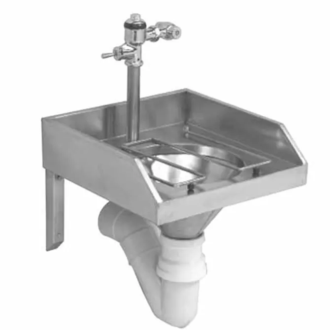
Standard commercial sinks lack the flushing velocity, drain clearance, and basin depth that clinical waste demands. For a proper dirty utility room, you choose between a compact wall-mounted slop sink and a combined hospital sluice sink.
The decision depends on your room footprint, staff task load, and whether you need a separate manual wash bowl integrated into the same unit.
Before finalizing your sluice room design, consult the full hopper sink sizing and drainage criteria for healthcare and facility projects to match rough-in plumbing positions with your soil stack layout.
| Technical Property | Wall-Mounted Slop Sink (PQ219) | Combined Hospital Sluice Sink (KC-12060) |
|---|---|---|
| Primary application | Liquid waste disposal and bedpan flushing in compact dirty utility rooms, clinic back-of-house, and care home service areas | Multi-function dirty utility suites requiring both flushing disposal and a separate manual rinse or soak bowl |
| Basin design | Conical slop hopper funnel, ø350 mm internal diameter, with continuous flushing rim | Conical flushing hopper (ø350 mm) plus adjacent rectangular wash bowl, 500 × 400 × 200 mm |
| Cistern configuration | Wall-mounted high-level cistern, 6 to 9 litre flush volume, exposed or concealed | Integrated cistern, rear-access service panel, matched to combined unit body |
| Material standard | Grade 304 SS, 1.2 to 1.5 mm sheet; Grade 316 available for high-chlorine environments | Grade 304 SS, 1.5 to 2.0 mm sheet; Grade 316 on request |
| Installation type | Wall-mounted, optional front support legs; 150 mm floor clearance standard | Heavy wall-bracket frame or floor-standing configuration |
| Rear splashback | Flat upstand, 150 mm standard | Integrated deep splashback, 300 mm, protecting drywall from aerosol spray |
| Typical project fit | Ward closets, outpatient clinic rooms, care home utility rooms, tight sluice room designs | Main dirty utility rooms in acute wards, surgical day units, larger residential care blocks |
Request technical datasheets for both models before you finalize your room drawing. You can customise dimensions, outlet positions, and cistern heights to match existing plumbing centres.
HTM64 Rules for the Clinical Wash-Hand Basin
Washing hands in a sink used for bedpan disposal constitutes a clinical infection control failure. Aerosol droplets from the disposal process carry viable organisms. A separate, dedicated clinical wash-hand basin in Zone 3 eliminates this risk. HTM64 specifies three non-negotiable design criteria for this basin:
- No tap holes in the basin deck. Specify wall-mounted taps positioned above the basin. Deck-mounted taps create horizontal joint lines where standing water pools. Pseudomonas aeruginosa colonises tap bodies through these wet joints and can survive standard surface disinfection routines.
- No overflow cavity. The basin inner bowl must carry a smooth, continuous surface with no overflow channel. Overflows trap stagnant water behind the visible ceramic or steel surface, where biofilm establishes in as little as 48 hours and resists chlorine-based disinfectants at standard dilution.
- No plug or chain. The waste outlet remains open and free-draining. Staff cannot fill the basin with standing water, which forces all hand washing to occur under flowing water only, reducing the bacterial load transferred to the basin surface.
Tap Specification for the Dirty Utility Room
All taps in the dirty utility room, including those serving the slop sink area, must operate without hand contact. Specify wall-mounted electronic infrared sensor taps or elbow-action lever taps with a minimum 200 mm lever length. Set the thermostatic mixing valve to TMV3 standard, delivering water between 38°C and 41°C. Point the outlet downward toward the drain. Forward-facing outlets scatter droplets across the basin surface.
Material and Structural Requirements for Wet Clinical Spaces
The combination of chlorine-releasing disinfectants, daily pressure hosing, and heavy impact from mop buckets and equipment trolleys degrades inferior materials within two to three years.
Steel Grade and Sheet Thickness
Grade 304 stainless steel covers the majority of UK hospital specifications. Upgrade to Grade 316 if your infection control team uses sodium dichloroisocyanurate (NaDCC) tablets above 1,000 ppm daily, or if the facility sits within two kilometres of a coastal environment. Sheet thickness below 1.2 mm flexes under load, fracturing welded seams and breaking the silicone seal between the unit and the wall. Once moisture penetrates behind a stainless steel panel, the drywall substrate deteriorates and re-colonisation risk rises.
Coved Corners and Weld Finish
All internal corners in slop sink bowls and countertop upstands must carry a minimum 10 mm radius cove. CSSD-adjacent spaces and any utility room subject to decontamination validation require this geometry: a flat-bottomed square corner resists standardised wipe tests and holds residue that passes visual inspection but fails ATP swab checks. Specify heli-arc welded seams, ground flush and polished to a consistent 180-grit satin finish across all external surfaces.
Wall Cladding and Floor Clearance
Cover wet zones with 1.2 mm Grade 304 stainless steel wall-cladding panels behind the slop hopper, extending to a minimum of 1,200 mm above the rim. This protects the plasterboard substrate from aerosol penetration. Standard ceramic tile installations fail to achieve this at grout lines.
Mount all wall-hung disposal units with heavy-duty brackets leaving at least 150 mm of floor clearance. Floor-scrubbing machines require this gap. Where facilities use manual mopping, 100 mm clearance is the absolute minimum. Legs or plinths flush with the floor create dirt-trapping voids that no mop head reaches.
Sluice Room Design: Common Specification Mistakes
Architects and project procurement teams repeat several predictable errors on first-time sluice room designs.
- Placing the handwash basin on the same wall as the hopper Staff using a slop hopper generate aerosol spray at rim level. A clinical wash-hand basin within 600 mm of the hopper receives contaminated droplets on its inner surface, defeating the purpose of the dedicated hand hygiene zone.
- Specifying a 50 mm waste outlet A 50 mm outlet cannot clear the viscosity of clinical waste. Specify a minimum 100 mm waste outlet on all slop hoppers, matched to a 100 mm soil branch connection. A 100 mm outlet clears the trap fully with a single 6-litre flush, leaving no residue in the trap seal.
- Omitting a dedicated sluice room ventilation extract HTM64 requires the dirty utility room to operate at negative pressure relative to the access corridor. An extract rate of 10 air changes per hour prevents airborne pathogens from migrating into clean utility areas or patient bays through gaps under the door.
- Forgetting drainage alignment before the unit shipsConfirm the waste outlet centre position, outlet direction (vertical or horizontal), and floor-to-outlet height with the manufacturer before fabrication. Field modifications to drainage centre positions add cost and delay in renovation projects where the existing soil stack position is fixed.
Sluice Room Procurement Checklist
Use this list when preparing your technical submittal or tender schedule:
- Primary fluid disposal unit: Specify a PQ219 compact wall-mounted slop sink (540 × 540 mm body) for ward closets and care home rooms. Specify a KC-12060 combined unit for main acute dirty utility rooms requiring a dual-function body.
- Clinical wash-hand basin: HTM64-compliant, no overflow, no deck tap holes, wall-mounted elbow-action or sensor taps, TMV3 valve, open waste outlet.
- Wall cladding panels: Grade 304 SS, 1.2 mm, covering all wet-zone walls to 1,200 mm above highest fixture rim.
- Drainage: 100 mm waste outlet on the disposal unit, 40 mm on the hand basin, both connected to dedicated soil branches, separate from ward sanitary pipework.
- Room ventilation: Dedicated negative-pressure extract, minimum 10 air changes per hour, louvred door undercut for passive air make-up.
- Macerator (where specified): Position within 400 mm of the slop hopper to minimise open-container travel distance. Confirm that the macerator drain line connects to a separate macerated-waste soil branch to prevent blockages in standard soil stacks.
Submit your room layout drawings, plumbing centres, and fixture schedule to Xinhe’s technical team for sizing review and CAD confirmation via the project contact portal.